Defect Formation in Variable-Stiffness Composites: Fiber Buckling and Wrinkling Limits in Small-Tow Robotic Steering
A Technical Review of Physical Steering Limits in Continuous Fiber Robotic Placement
Executive Summary
Variable-angle tow (VAT) steering technology represents a paradigm shift in composite manufacturing, enabling the creation of structures with spatially varying stiffness properties that align with principal stress directions. However, this capability is fundamentally constrained by the formation of process-induced defects when fiber paths exceed critical curvature limits. Unlike large-scale aerospace automated fiber placement (AFP) machines that predominantly use 6.35 mm (0.25 inch) wide tapes, emerging robotic systems like the AddX employ small-tow configurations (1k-3k carbon fiber) that exhibit distinctly different steering behavior.
This review investigates the minimum steering radius (MSR) threshold beyond which steering-induced defects—particularly fiber buckling, tow wrinkling, and pull-up phenomena—compromise structural integrity. Current research indicates that MSR for continuous fiber tapes ranges from 600-1500 mm for 6.35 mm wide tapes, with narrower tows achieving radii as tight as 100-280 mm under optimal conditions [1]. The interaction between tow geometry (width, thickness, fiber count), matrix rheology (viscosity, tack), and process parameters (tension, heating, compaction) determines the practical limits of steerability.
While extensive research characterizes defect formation in aerospace-scale AFP systems (12k-24k tows, >5 mm widths), the micromechanical behavior of small-tow robotic systems (1k-3k, <3 mm) remains under-documented. This review synthesizes emerging data on the unique steerability characteristics of lightweight robotic placement systems and their implications for structural design.
1. Introduction
1.1 Variable-Stiffness Composites and Fiber Steering
Traditional composite laminates employ straight fiber architectures with discrete ply orientations (0°, 90°, ±45°), resulting in uniform stiffness properties across the structure. Variable-angle tow (VAT) composites break this constraint by continuously varying fiber orientation within individual plies, creating tailored stiffness distributions that improve structural efficiency by 15-40% for buckling-critical applications [6].
The manufacturing enabler for VAT composites is tow steering—the controlled in-plane curving of continuous fiber paths during automated layup. In automated fiber placement (AFP), a robotic head deposits prepreg tapes along prescribed curvilinear trajectories, with individual fibers following geodesic-like paths on the tool surface. However, steering introduces a fundamental geometric incompatibility: when a tow of finite width follows a curved path, fibers on the inner radius experience compression while outer-radius fibers are placed under tension.
1.2 The Small-Tow Advantage and Challenge
Conventional aerospace AFP systems use tows ranging from 6.35 mm (0.25 inch, ~12k carbon fiber) to 76 mm (3.0 inch, multiple tows) in width. These systems are optimized for large structures (wing skins, fuselage panels) where placement speed is prioritized over geometric flexibility. In contrast, emerging robotic systems target smaller structures with complex geometries—pressure vessels, drone frames, prosthetics—where tight steering radii are essential.
Small-tow systems (1k-3k carbon fiber, 1-3 mm width) offer superior drapability due to reduced bending stiffness scaling as width³ [7]. CompositesWorld reports that 3.175 mm tapes achieve MSR of ~635 mm, while Ingersoll's R&D systems have demonstrated 150 mm radii for 12.7 mm tapes under controlled conditions [8]. However, small tows introduce new challenges: reduced tack area increases bridging susceptibility, higher placement speeds amplify dynamic tension variations, and thermoplastic matrices (PA, PEEK) exhibit different consolidation behavior at the reduced scale.
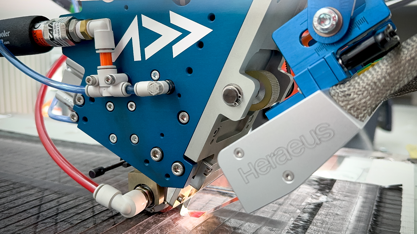
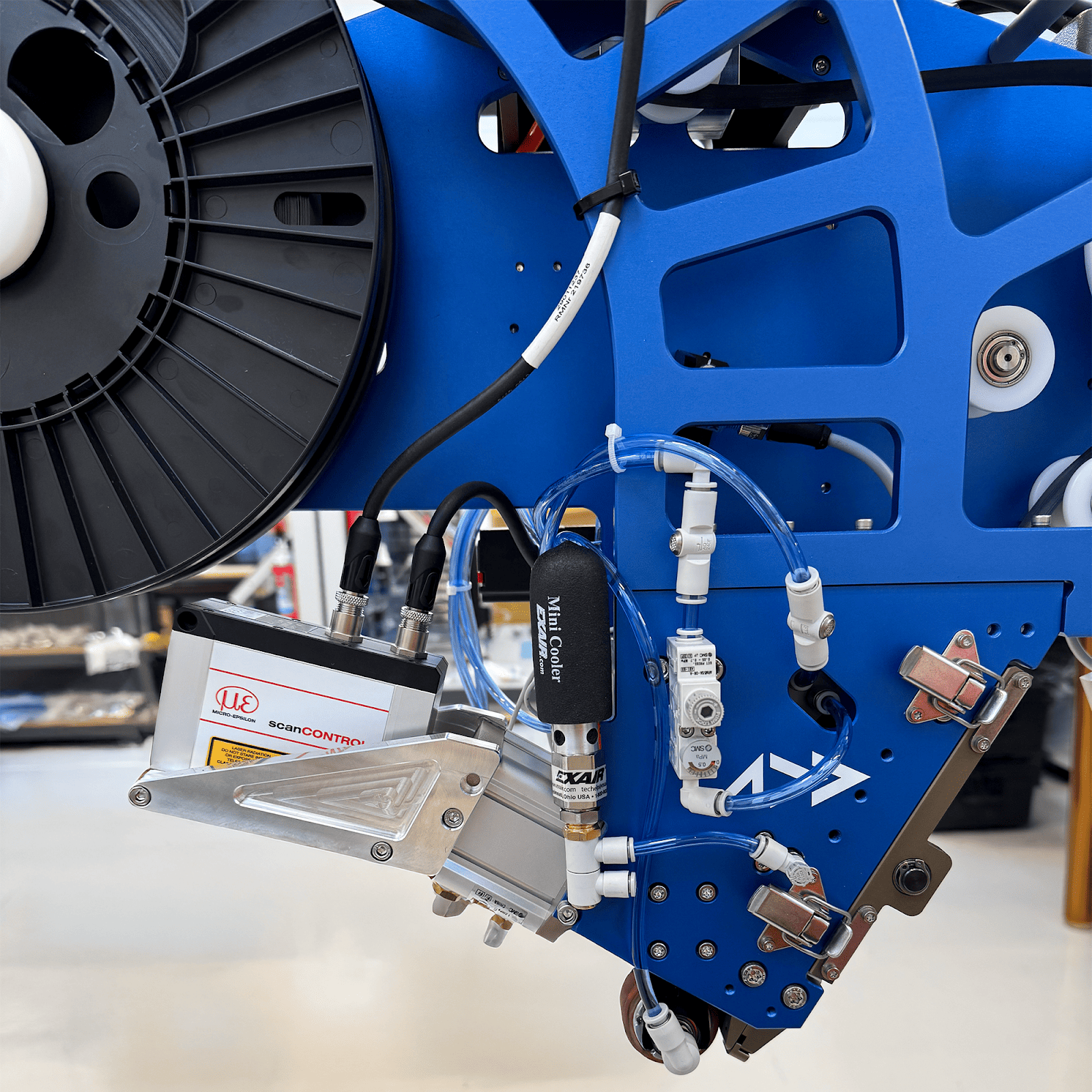
Addcomposites AFP-XS System
Addcomposites AFP-XS system integrated with industrial robot for advanced small-tow composite manufacturing.
1.3 Research Objective and Scope
This review establishes a comprehensive framework for understanding steering-induced defect formation in small-tow robotic placement systems. We address:
Mechanics: In-plane bending forces, stress states, and geometric constraints during curved-path deposition
Defects: Classification of buckling, wrinkling, pull-up, gaps, and overlaps with formation mechanisms
Materials: How tow size (1k vs 12k) and matrix viscosity (PA vs PEEK) affect critical steering radius
Modeling: Analytical and numerical approaches for predicting defect onset from path curvature
Mitigation: Process parameter optimization (tension, heating, compaction) to extend steering limits
The review synthesizes data from aerospace AFP literature while highlighting scaling considerations for small-tow robotic systems, providing design engineers with quantitative guidelines for manufacturability-constrained optimization.
2. Mechanics of Steering
2.1 Geometric Fundamentals of Tow Steering
When a tow of width w follows a curved path with radius of curvature R (measured to the tow centerline), the inner and outer edges traverse different path lengths over arc length s:
Path length (inner) = s · (R - w/2) / R
Path length (outer) = s · (R + w/2) / R
This geometric incompatibility generates a strain differential: Δε = w / R
For a 3 mm wide tow on a 500 mm radius path, Δε = 0.006 (0.6% strain difference). Assuming fiber-dominated response, this translates to stress differential: Δσ ≈ E_fiber · Δε. For carbon fiber (E ≈ 230 GPa), this yields ~1380 MPa differential—significant compared to typical consolidation pressures (0.5-2 MPa) and tack adhesion strengths (0.1-0.5 MPa).
2.2 Force Distribution During Steering
During curved-path deposition, the tow experiences distinct force regimes:
Tensile Forces (Outer Radius)
- Applied tension from payout system (5-20 N typical for small tows)
- Centrifugal force from path curvature (usually negligible at placement speeds <0.5 m/s)
- Fiber elongation due to path length differential
Compressive Forces (Inner Radius)
- Geometric shortening relative to centerline path
- Resistance to buckling from matrix confinement
- Lateral confinement from adjacent fibers
The critical insight: when compressive forces exceed the critical buckling load of the confined fiber bundle, out-of-plane deformation initiates—manifesting as fiber buckling or tow wrinkling.
2.3 Critical Steering Radius Derivation
The minimum steering radius can be approximated using Euler buckling theory adapted for lateral confinement. For a tow of width w, thickness t, with compressive modulus E_c and lateral confinement stiffness k_lateral (representing matrix constraint):
R_critical ≈ w · sqrt(E_c · t / k_lateral)
This simplified expression reveals key dependencies:
More refined models (Section 5) incorporate tow tension, temperature-dependent matrix properties, and time-dependent consolidation effects.
2.4 Real-World Data: Experimental Steering Limits
Empirical studies across different tow widths and material systems demonstrate:
Thermoset Prepregs (Epoxy Matrix, Room Temperature Layup)
Thermoplastic Tapes (PEEK Matrix, Laser-Heated at 380-420°C)
The thermoplastic increase (~33% larger MSR) stems from lower matrix viscosity at placement temperature, reducing lateral confinement and increasing buckling susceptibility.
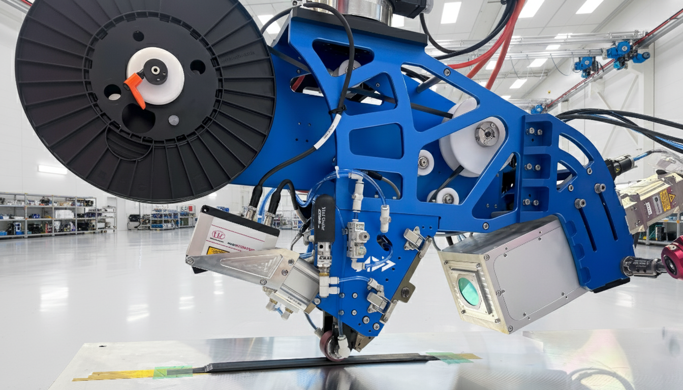
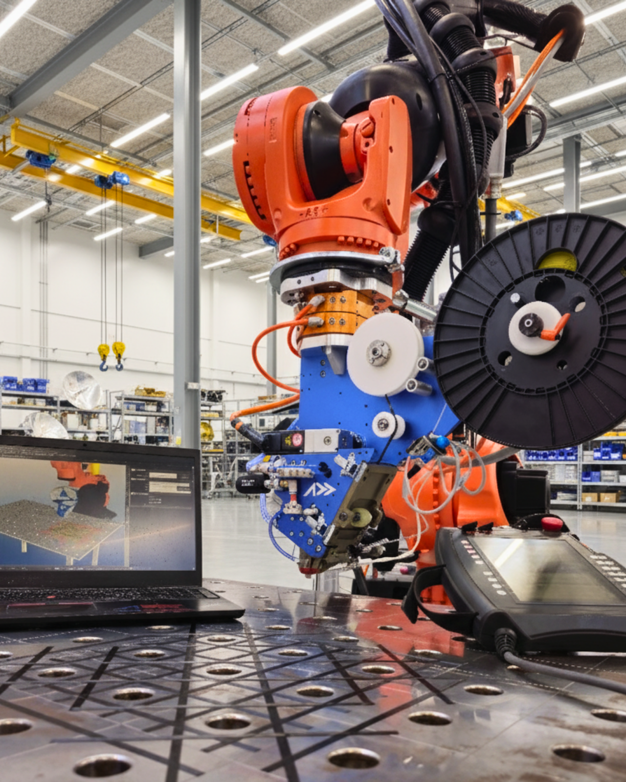
Superior Steering Capability
Addcomposites robotic AFP system placing variable-angle tows on complex curved surfaces with superior steering capability.
3. Defect Taxonomy
3.1 Fiber Buckling (Out-of-Plane Waviness)
Description: Individual carbon fibers develop sinusoidal out-of-plane undulations within the tow cross-section. Wavelengths typically range from 2-10 mm with amplitudes of 0.1-0.5 mm.
Formation mechanism: When inner-radius fibers experience compressive strain exceeding ~0.3-0.5%, matrix confinement is insufficient to prevent Euler buckling. The fiber "escapes" compression by developing perpendicular waviness. Critical for stiff fibers (carbon E ≈ 230 GPa) in low-viscosity matrices.
Structural Impact [2]
Detection: Cross-sectional microscopy reveals fiber misalignment; ultrasonic C-scan shows attenuation anomalies; X-ray CT provides 3D fiber tracking.
Fiber Steering Defect Mechanism
Compressive buckling and resin pocket formation during curved tow placement
3.2 Tow Wrinkling (In-Plane and Out-of-Plane)
Description: The entire tow width develops macroscopic folds or pleats perpendicular to fiber direction. Distinguished from fiber buckling by collective behavior—all fibers in affected region deform together. Two subtypes:
In-Plane Wrinkling
- Tow develops serpentine shape on tool surface without lifting
- Wavelength: 20-100 mm
- Critical radius ratio: R/w < 150-200 [1]
- Common in wide tows (>6 mm) with moderate steering
Out-of-Plane Wrinkling
- Tow lifts from substrate forming standing waves
- Wavelength: 10-50 mm
- Height: 0.5-2 mm above surface
- Occurs at R/w < 100 or with inadequate compaction pressure [1]
Formation mechanism: Unlike fiber buckling (material instability), wrinkling is a geometric instability—the tow physically cannot conform to the mandated curved path without developing excess length on the inner radius. When this excess length exceeds the tow's in-plane shear capacity (~2-5° shear angle for unidirectional prepreg), the tow "folds" to relieve strain energy.
Key parameter: Critical wrinkle strain [4]: ε_critical ≈ w / (2 · R). When steering-induced compressive strain on inner edge exceeds this threshold, wrinkles initiate. For a 6 mm tow on 600 mm radius: ε = 6 / (2 · 600) = 0.005 (0.5%). This aligns with empirical observations of wrinkle onset at R/w ≈ 100-200.
Structural Impact
Fiber Buckling vs. Tow Wrinkling
Two distinct compressive defect modes during curved AFP tow placement
3.3 Pull-Up Defects
Description: The tow locally detaches from the substrate during or after placement, creating bridged regions with no substrate contact. Distinct from wrinkling in that the tow remains relatively straight but is elevated above the surface.
Formation mechanism: Two primary causes: Springback during steering—bent tow stores elastic energy; if tack adhesion is insufficient, release of internal stresses lifts the tow from substrate. Tool surface curvature incompatibility—on compound-curved surfaces (varying curvature in both directions), the tow path may not be geodesic, inducing out-of-plane forces.
Critical factors: Tack force must exceed elastic restoring force: F_tack > k_bending · (w/R)². For low-tack materials (thermoplastics, aged prepreg), pull-up occurs at larger radii than defect-free placement. Dynamic effects: Placement speeds >0.3 m/s reduce dwell time for tack development, increasing pull-up susceptibility [9].
Structural Impact
Detection: Laser profilometry during layup; thermography shows temperature anomalies at bridged zones; tactile inspection post-cure.
3.4 Gap Defects
Description: Intentional or unintentional spacing between adjacent tow edges, creating uncovered substrate regions. In VAT layup, gaps form naturally when tows following diverging curved paths separate.
Geometric formation [3]: On a concave surface (tows curving away from each other), adjacent tow edges separate as: Gap width = s · |1/R_1 - 1/R_2| · w. For two 3 mm tows on 500 mm and 600 mm radii over 200 mm arc length: Gap = 200 · |1/500 - 1/600| · 3 ≈ 0.2 mm. Gaps accumulate over path length—long curved trajectories can generate 1-2 mm gaps requiring coverage strategies.
Structural Impact [15]
Mitigation: Course shifting (progressively offset tow starting positions), cut-restart sequences, or accepting gaps and backfilling in subsequent plies [14].
Concave vs. Convex Steering Defects
Gap and overlap formation mechanisms during adjacent tow placement on curved paths
3.5 Overlap Defects
Description: Adjacent tows deposited along converging curved paths overlap, creating local thickness buildups (1.5-2× nominal ply thickness).
Geometric formation: Inverse of gap scenario—on convex surfaces, tows converge: Overlap width ≈ s · |1/R_1 - 1/R_2| · w. Same parameters as gap equation; convex curvature (tows approaching) yields positive overlap.
Structural Impact
Acceptance criteria: Aerospace standards (Boeing, Airbus) typically limit overlaps to <50% tow width or <0.5 mm absolute depending on structural criticality.
3.6 Defect Interaction and Compound Effects
Real-world steering-induced defects rarely occur in isolation:
Buckling + Pull-up: Fiber buckling reduces effective tow stiffness, increasing susceptibility to springback lift-off
Wrinkling + Gaps: Severe wrinkling causes tow width reduction (perpendicular compression), creating secondary gap defects
Gaps + Overlaps: Steering path optimization may trade gap defects for overlap defects depending on surface curvature
These interactions complicate both prediction and mitigation—models addressing single defect modes underestimate real manufacturing constraints.
4. Material Influence
4.1 Tow Size Effects: 1k vs 3k vs 12k Carbon Fiber
Carbon fiber tows are designated by filament count: 1k = 1,000 fibers, 3k = 3,000 fibers, 12k = 12,000 fibers. For equivalent fiber type (e.g., T700S), tow cross-sectional area and width scale linearly with fiber count.
Mechanical Implications for Steering
Bending stiffness scales as width³ [7]:
This 64× stiffness difference between 1k and 12k tows dramatically affects steering behavior. Critical buckling load: P_cr ∝ E · I / L². For constant fiber length, 12k tows resist buckling 64× more than 1k—but also require 64× higher force to bend along curved paths.
Empirical Steering Radius Data
| Tow Size | Typical Width | Min Steering Radius (Thermoset) | Min Steering Radius (Thermoplastic) |
|---|---|---|---|
| 1k | 1.5 mm | 100-150 mm | 150-230 mm |
| 3k | 3.0 mm | 280-450 mm | 380-580 mm |
| 12k | 6.35 mm | 600-900 mm | 800-1200 mm |
| 24k | 12.7 mm | 1200-1800 mm | 1500-2200 mm |
Sources: [8, 16, 19]
Key Finding
Small tows (1k-3k) enable 90% reduction in minimum steering radius compared to aerospace-standard 12k tows, making them ideal for robotic systems targeting complex geometries.
Trade-offs
4.2 Matrix Systems: Thermoset vs Thermoplastic
The matrix material fundamentally alters tow steering behavior through viscosity and tack characteristics:
Thermoset Prepregs (Epoxy, BMI, Cyanate Ester)
- Room temperature viscosity: 10³-10⁵ Pa·s (partially cured B-stage resin)
- Tack mechanism: Surface adhesion from uncured resin + mechanical interlocking
- Steering advantage: High tack provides strong lateral confinement, resisting fiber buckling
- Limitation: Limited out-time (days to weeks); requires refrigerated storage
Thermoplastic Tapes (PA6, PA12, PEEK, PPS)
- Room temperature: Solid (no tack)
- Processing temperature viscosity: 10²-10³ Pa·s at melt point (380°C for PEEK)
- Tack mechanism: Thermal welding via localized heating (laser, hot gas torch)
- Steering challenge: Low viscosity at placement temp reduces lateral confinement by 10-30× [19]
- Benefit: Unlimited shelf life; weldability; recyclability
Comparative Steering Performance [19]
For 6.35 mm wide carbon/PEEK vs carbon/epoxy on identical 800 mm radius path: Epoxy prepreg (room temp) achieves defect-free placement with compaction roller at 0.7 MPa. PEEK tape (laser-heated to 400°C) shows out-of-plane wrinkling observed; required 1.2 MPa compaction and reduced placement speed (0.15 m/s → 0.08 m/s).
Thermoplastic mitigation: Hot gas torch-assisted AFP maintains matrix temperature in semi-molten state (300-350°C for PEEK) during placement, increasing effective viscosity and improving consolidation [19]. This extends MSR by 20-35% compared to rapid laser heating + immediate cooling.
4.3 Hybrid Systems: Multi-Material Tows
Emerging research explores hybrid tows mixing carbon with glass or thermoplastic fibers to tune steering behavior:
Carbon-glass hybrids: Replacing 20-30% carbon with glass (E ≈ 70 GPa) reduces effective tow modulus. Lower buckling resistance but also lower internal stresses during steering. Net effect: Minimal change to MSR but improved impact tolerance [17]
Carbon-thermoplastic fiber blends: Commingling carbon with meltable polymer fibers (PA, PP). During heated placement, polymer fibers melt and infiltrate carbon bundle. Provides in-situ matrix formation + increased tack via polymer welding. Reported MSR improvement: 15-25% vs dry fiber placement [18]
Minimum Steering Radius by Material & Tow Size
Smaller radius = tighter curves achievable without defects (standard ¼" tow reference)
5. Predictive Modeling
5.1 Analytical Models: Critical Buckling Load Theory
The most widely adopted analytical framework treats the inner-radius fiber bundle as a laterally confined beam under compression [4, 10]. Key assumptions: Euler-Bernoulli beam theory (fibers are slender), lateral confinement from matrix with elastic foundation stiffness k, and geometric nonlinearity from path curvature strain: ε = w/(2R).
Critical Buckling Load Derivation [10]
For a fiber bundle of width b, thickness t, modulus E, confined by matrix with foundation stiffness k:
P_cr = 2 · sqrt(k · E · I)
Where I = b·t³/12 for rectangular cross-section
Solving for critical radius: R_cr = (3 · w · sqrt(E)) / (2 · sqrt(k · t))
Key insights:
Foundation Stiffness Estimation [4]
This 10× difference explains the observed MSR increase for thermoplastics.
Model Validation [4]
Belhaj & Hojjati (2018) tested carbon/epoxy prepreg (6.35 mm width) with k = 1.2 MPa: R_cr_predicted ≈ 680 mm. Experimental MSR: 650-720 mm → Model accuracy: ~10%.
5.2 Numerical Models: Finite Element Analysis
For complex geometries (compound curvature, variable tension, thermal gradients), analytical models are insufficient. Finite element (FE) simulations provide high-fidelity predictions at computational cost.
Explicit Dynamics [20, 21]
- Treats tow as deformable body with orthotropic material properties
- Simulates placement process step-by-step: tow payout → bending → contact with substrate → consolidation
- Captures dynamic effects (placement speed, roller interaction, inertial forces)
- Typical mesh: 50,000-200,000 elements for single tow path
Implicit Static [13]
- Assumes quasi-static equilibrium at each placement position
- Faster computation but neglects transient effects
- Suitable for initial design screening, not final validation
Representative Material Properties for Carbon/Epoxy FE Model
| Property | Value |
|---|---|
| E_longitudinal | 130 GPa (fiber-dominated) |
| E_transverse | 7 GPa (matrix-dominated) |
| G_12 | 4 GPa (shear modulus) |
| Density | 1550 kg/m³ |
| Matrix foundation | Spring elements with k = 0.5-2 MPa |
Defect Prediction Workflow [21]
Input
CAD tool surface + planned fiber paths (curvature schedule)
Pre-processing
Mesh tow geometry, assign material properties, define contact interfaces
Simulation
Incrementally deposit tow along path, monitor stress/strain at each step
Post-processing
- Identify regions where compressive strain > ε_critical (buckling risk)
- Out-of-plane displacement > tolerance (wrinkling/pull-up)
- Gap width > acceptance threshold
Path Correction
Modify fiber paths to remain within defect-free envelope
Computational cost: High-fidelity FE simulation of single 1-meter tow path requires 2-8 hours on workstation (16-core CPU) [20]. For full component with hundreds of paths, computational expense is prohibitive—leading to hybrid approaches.
5.3 Hybrid Approaches: ML-Accelerated Defect Prediction
Recent work combines analytical models (fast, low-fidelity) with machine learning trained on FE data (accurate, slow) to enable real-time manufacturability assessment [28].
Workflow [28]
Reported Accuracy [28]
Application example: For complex pressure vessel (ellipsoidal dome with R varying from 200-800 mm), traditional FE requires 40-60 hours; ML-accelerated approach completes manufacturability assessment in <10 minutes.
Critical Buckling Load vs. Steering Radius
Operating below Pcr at a given radius prevents fiber buckling defects — intersection defines Rcr
6. Mitigation Strategies
6.1 Tension Control
Mechanism: Applying controlled tensile load to the tow during placement pre-stresses fibers, offsetting steering-induced compression and delaying buckling onset.
Optimal Tension Range [5, 9]
Implementation: Servo-controlled payout systems with inline load cells provide real-time tension feedback [9]. Advanced systems use predictive control—feed-forward tension adjustment based on upcoming path curvature to prevent dynamic oscillations.
Experimental Validation [9]
Carbon/epoxy 3k tow, 3 mm width, 400 mm radius: Baseline tension (5 N) showed buckling defects. Optimized tension (12 N) achieved defect-free placement. Over-tensioned (22 N) caused fiber breakage at 18% of test samples.
6.2 Localized Heating
Mechanism: Laser or hot gas torch heating reduces matrix viscosity in the steering zone, decreasing lateral confinement stiffness k and paradoxically increasing buckling resistance by allowing more in-plane shear accommodation.
Thermoplastic Processing [19]
For PEEK tapes, laser heating to 380-420°C (above melt point 343°C): Matrix viscosity drops from 10³ → 10² Pa·s. Enables intimate contact and welding to substrate. But: Reduces k by 60-80%, worsening buckling susceptibility.
Solution: Controlled cooling profile [19]—Laser spot heating at 400°C at placement point, immediate compaction roller contact (cold roller at 80°C), rapid cooling to 250°C within 2-3 seconds. Partially re-solidified matrix provides confinement while maintaining consolidation.
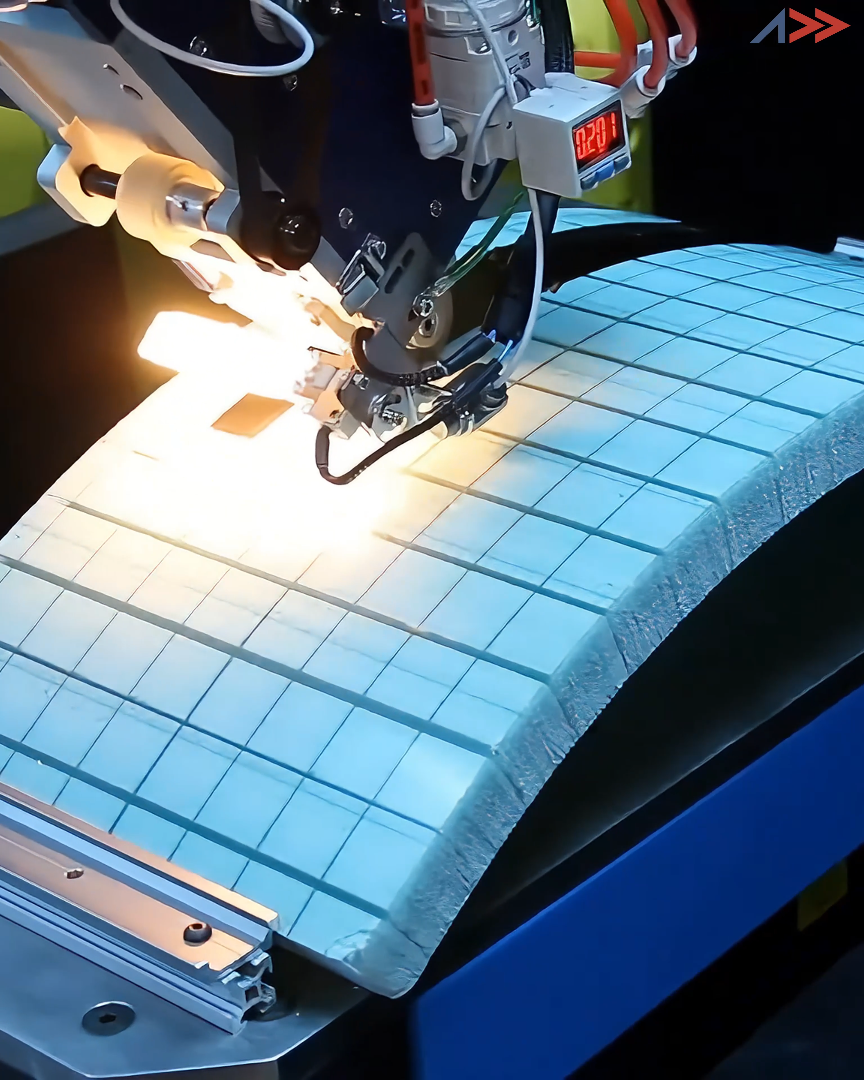
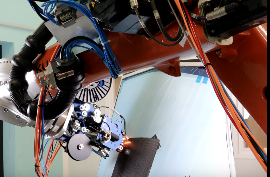
Laser Power Optimization
Addcomposites AFP system with integrated laser heating for thermoplastic composite processing.
6.3 Compaction Pressure Management
Mechanism: Roller compaction during placement ensures tow-substrate adhesion and promotes consolidation. Optimal pressure balances tack development vs fiber distortion.
Pressure Ranges [24]
Roller Geometry
Diameter: 50-100 mm typical; larger rollers distribute load, smaller conform to tight radii. Width: 1-2× tow width for uniform pressure. Material: Silicone (compliant, conforms to defects) vs metal (stiff, requires precise surface).
Trade-off: Higher compaction improves consolidation but exacerbates fiber buckling by constraining out-of-plane escape paths. Optimal pressure window narrows at tight steering radii.
6.4 Path Planning Optimization
Rather than adapt process parameters to accommodate aggressive steering, an alternative approach is constrained path optimization—designing fiber paths that respect manufacturability limits.
Steering Constraint Formulation [23]
|∇θ| ≤ 1 / R_min
Where R_min is the minimum allowable radius (material-dependent). This inequality becomes a constraint in structural optimization: Objective—minimize weight (or maximize buckling load). Design variables—fiber angle distribution θ(x, y). Constraints include stress limits, buckling eigenvalue > 1.0, and manufacturability: |∇θ| ≤ 1/R_min (steering limit).
Impact on Structural Performance [23]
For rectangular plate optimized for uniaxial compression buckling:
Conclusion: Tight steering capability directly translates to structural efficiency. Small-tow systems (R_min ~ 200-300 mm) capture 80-90% of VAT benefits vs aerospace systems (R_min ~ 800-1200 mm) limited to 40-60%.
Shift-and-Steer Hybrid Paths [3]
To manufacture tight-radius features: Steer to maximum allowable curvature (approach minimum radius asymptotically), cut and restart when tow edge reaches target position, shift starting position for next course to fill gaps, repeat until feature is covered. This strategy introduces cut-restart overhead (2-5 second penalty per cut) but enables near-geodesic paths on complex surfaces without exceeding MSR.
6.5 In-Process Defect Detection and Correction
Real-Time Defect Detection
Addcomposites AFP-XS equipped with laser line scanner for real-time defect detection during variable-angle tow placement. High-resolution scanning enables precise wrinkle and gap detection.
Online Monitoring [27]
Real-time defect detection enables adaptive process correction:
Structured Light Scanning
- Projects laser line onto tow surface; camera captures profile
- Detects: Wrinkling (height >0.3 mm), pull-up (bridging), gaps/overlaps
- Resolution: 0.05 mm vertical, 0.1 mm lateral
- Speed: 10-30 Hz scan rate (compatible with 0.2-0.5 m/s placement)
Thermography
- Infrared camera monitors temperature distribution
- Hot spots indicate: Inadequate compaction (poor heat transfer to substrate)
- Cold spots indicate: Tow bridging (air gap insulation)
- Thermal history: Detects cure state variations in thermosets
Deep Learning Classification [27]
Convolutional neural networks (CNNs) trained on labeled defect images: Input 224×224 pixel RGB/thermal image crop, output defect classification (buckling, wrinkle, gap, overlap, defect-free). Accuracy: 92-96% (validated on 5,000+ test samples). Inference speed: <30 ms per frame (enables real-time operation).
Closed-Loop Correction [27]
Upon defect detection:
Steering-Aware AFP Manufacturing Workflow
Closed-loop process from structural design through adaptive defect correction
7. Discussion
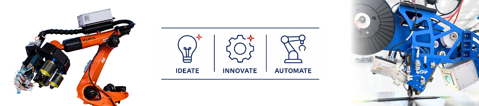
Democratizing Advanced Composites
Addcomposites democratizes advanced composite manufacturing with accessible robotic AFP systems. Small-tow capability enables complex geometries impossible with traditional aerospace installations.
7.1 Paradigm Shift: Accessibility vs Aerospace Precision
Traditional AFP (Boeing, Lockheed, Airbus)
- Large-area coverage (>1 m² parts)
- High placement rates (10-50 kg/hr)
- Ultra-tight tolerances (<0.1 mm)
- Million-dollar capital investment
Robotic Small-Tow Systems
- Complex geometries (<0.5 m characteristic dimension)
- Moderate placement rates (0.5-5 kg/hr)
- Relaxed tolerances (0.3-0.5 mm acceptable)
- Accessible capital ($50-200k systems)
The Steering Capability Gap
Aerospace AFP: R_min ≈ 800-1500 mm (limited by 12k-24k tows). Robotic AFP: R_min ≈ 150-400 mm (1k-3k tows enable 90% tighter radii). This difference unlocks applications impossible for traditional systems: Pressure vessels (ellipsoidal domes with R ~ 200-400 mm), Prosthetics (anatomically contoured shapes with R ~ 100-300 mm), Drone frames (optimized load paths with R ~ 150-250 mm).
7.2 Small-Tow Challenges and Research Gaps
Despite steering advantages, small-tow systems face distinct challenges:
Placement rate penalty: 1k tow covers 1/12 area of 12k → requires 12× more passes. Partially offset by higher allowable speeds. Net throughput: 2-5× slower.
Tack and bridging: Reduced contact area → lower tack forces. More susceptible to pull-up on compound-curved surfaces. Requires higher compaction pressure.
Fiber fuzz and debris: Smaller tows have higher surface area-to-volume ratio. Edge fibers more prone to damage during handling/cutting.
Limited material availability: Most prepreg manufacturers optimize for 6-12 mm widths. Small-tow formats often custom orders (higher cost, minimum quantities).
Research Gaps
7.3 Design Guidelines for Robotic VAT Manufacturing
Based on synthesized literature, recommended design practices for small-tow robotic AFP:
For 3k Carbon/Epoxy Prepreg (3 mm Width, Typical System)
| Design Feature | Recommendation | Rationale |
|---|---|---|
| Minimum steering radius | R_min ≥ 300 mm | Conservative limit ensuring <1% defect probability [1, 4] |
| Aggressive steering | R_min = 200-250 mm | Acceptable for non-critical structures; expect 2-5% local strength knockdown [2] |
| Course spacing | 2.5-2.8 mm | 15-25% overlap prevents gap accumulation on curved paths [14] |
| Maximum gradient | |∇θ| ≤ 0.003 rad/mm | Equivalent to R_min = 300 mm constraint [23] |
| Ply drop angle | <5° | Steep angles (>5°) create wrinkle-prone regions requiring cut-restart |
| Compaction pressure | 0.5-0.8 MPa | Balance consolidation vs fiber damage [24] |
| Tension | 10-15 N | Optimized for 3k tow; scale linearly with fiber count [9] |
For 1k Carbon/Thermoplastic Tape (1.5 mm Width, Emerging Systems)
| Design Feature | Recommendation | Rationale |
|---|---|---|
| Minimum steering radius | R_min ≥ 150 mm | Leverages small-tow advantage; thermoplastic penalty ~+30% vs thermoset [19] |
| Heating | Laser 60-120 W, spot 4-6 mm | Maintain 380-420°C at placement point [19] |
| Compaction pressure | 1.0-1.5 MPa | Higher due to melt viscosity [19] |
| Cooling rate | 40-60°C/s | Rapid solidification improves crystallinity [18] |
| Tension | 6-10 N | Lower fiber count scales proportionally |
7.4 Structural Performance Impact: Knockdown Factors
For structural design allowables, steering-induced defects impose strength reductions: Allowable stress = Pristine strength × Knockdown factor
Fiber Buckling [2]
Tow Wrinkling [12]
Gaps and Overlaps [14, 15]
Design Implication: R/R_min Ratios
Tow Size Performance Comparison Matrix
Trade-off landscape across steering capability, productivity, and quality for standard AFP tow counts
| Parameter | 1k 1,000 filaments | 3k 3,000 filaments | 12k 12,000 filaments | 24k 24,000 filaments |
|---|---|---|---|---|
| Rmin (mm) |
★★★★
~150 mm
1k — Min Steering Radius
~150 mm — tightest curves, ideal for complex
geometries
|
★★★
~350 mm
3k — Min Steering Radius
~350 mm — good balance of steerability and width
|
★★
~750 mm
12k — Min Steering Radius
~750 mm — limited curvature, suits gentle contours
|
★
~1400 mm
24k — Min Steering Radius
~1400 mm — near-straight paths only
|
| Coverage Rate |
★
Slow
1k — Coverage Rate
Narrowest tow — many passes needed per ply
|
★★
Moderate
3k — Coverage Rate
3× wider than 1k, improved throughput
|
★★★★
Fast
12k — Coverage Rate
Standard production tow — high deposition rate
|
★★★★★
Fastest
24k — Coverage Rate
Maximum area coverage per pass — flat panels
|
| Surface Quality |
★★★★★
Excellent
1k — Surface Quality
Minimal gap/overlap — smoothest surface finish
|
★★★★
Very Good
3k — Surface Quality
Low defect density with well-managed parameters
|
★★★
Acceptable
12k — Surface Quality
Wider tow → larger gaps/overlaps on curved paths
|
★★
Limited
24k — Surface Quality
Significant defects on any steered path
|
| Material Avail. |
★★
Niche
1k — Material Availability
Specialty supply — limited prepreg formats
|
★★★
Standard
3k — Material Availability
Common aerospace grade — good supplier base
|
★★★★★
Broad
12k — Material Availability
Most common industrial format — wide selection
|
★★★★★
Broad
24k — Material Availability
Widely available — many industrial suppliers
|
| Cost / Area |
★★
High
1k — Cost per Area
Premium material + slow layup = high $/m²
|
★★★
Moderate
3k — Cost per Area
Balanced material cost and deposition rate
|
★★★★
Low
12k — Cost per Area
Economical material + fast coverage = low $/m²
|
★★★★★
Lowest
24k — Cost per Area
Maximum economy — ideal for large flat structures
|
Structural Knockdown Factor vs. Steering Radius Ratio
Strength retention as a function of R/Rmin — operating further above Rmin preserves laminate integrity
7.5 Future Directions
Emerging technologies:
AI-driven adaptive control [28]: Real-time defect prediction from sensor fusion (vision + thermal + force). Reinforcement learning optimizes process parameters path-by-path. Demonstrated 40% reduction in defect rate vs fixed-parameter layup.
Variable-width tow placement: Dynamically adjust tow width during placement (wide for straight, narrow for curves). Requires slit-tape or multi-tow control mechanisms. Potential to maintain constant R/w ratio → uniform defect risk.
Hybrid additive-subtractive: Over-deposit material in wrinkle-prone regions. CNC machine to final tolerance post-cure. Trades material waste for geometric precision.
Transverse fiber insertion: Supplemental stitching or Z-pins in steering zones. Suppresses delamination initiation at defect sites. 20-30% improvement in damage tolerance [15].
8. Conclusions
Variable-angle tow steering represents a transformative capability for composite manufacturing, enabling 15-40% structural efficiency gains through tailored fiber architectures. However, this potential is constrained by physics-based limits: when fiber paths exceed critical curvature thresholds, steering-induced defects—fiber buckling, tow wrinkling, and pull-up phenomena—compromise structural integrity with strength reductions up to 26.9%.
Key Quantitative Findings
Steering Radius Scaling
Minimum steering radius scales inversely with tow width: Small-tow robotic systems (1k-3k, 1-3 mm width) achieve R_min = 100-400 mm, enabling 90% tighter curvatures than aerospace AFP (12k-24k, 6-12 mm width, R_min = 600-1500 mm).
Matrix Rheology Dominance
Thermoplastic tapes require 20-35% larger radii than thermoset prepregs due to reduced lateral confinement at processing temperatures (10²-10³ Pa·s vs 10³-10⁵ Pa·s).
Predictive Models
Analytical buckling theory estimates defect onset within 10-15% accuracy; FE simulations provide high-fidelity validation. Machine learning acceleration enables real-time manufacturability assessment (seconds for full component).
Process Optimization
Active tension control (8-15 N optimal), localized laser heating (60-200 W for small tows), and adaptive compaction (0.5-2.5 MPa) collectively improve MSR by 15-30% without compromising part quality.
Manageable Knockdown Factors
Conservative design with R > 1.5·R_min limits strength reductions to <10%, preserving most of VAT's structural benefits while ensuring manufacturability.
Implications for Robotic Manufacturing
The emergence of accessible robotic AFP systems democratizes advanced composite manufacturing, but success requires:
Material Development
- Expanded availability of small-tow prepregs and thermoplastic tapes
Process Maturation
- Validated parameter windows for diverse material systems and geometries
Design Tools
- Integrated optimization frameworks incorporating manufacturability constraints from concept phase
Critical Knowledge Gaps
While aerospace-scale AFP is well-characterized, small-tow robotic systems operate in under-documented regimes:
Small-tow robotic AFP unlocks applications—complex geometries, low-volume production, distributed manufacturing—inaccessible to traditional aerospace systems. However, realizing this potential demands rigorous understanding of steering-induced defect physics and disciplined application of process controls. The minimum steering radius is not merely a manufacturing constraint but a fundamental design variable that couples material selection, geometry, and structural performance. Engineers embracing this reality will craft the next generation of lightweight, optimized composite structures.
References
[1] MDPI Aerospace (2022). "Formation Mechanism and Modeling Method of Wrinkling Defects in Variable Angle Tow Steering Fiber Placement." DOI:10.3390/aerospace9100620
[2] Cemenska, J. et al. (2023). "Damage and failure mechanisms of CFRP due to manufacturing induced wrinkling defects." Composites Part A, DOI:10.1016/j.compositesa.2023.107703
[3] Wu, W. et al. (2014). "Manufacturing characteristics of the continuous tow shearing method for manufacturing of variable angle tow composites." Composites Part A: Applied Science and Manufacturing, DOI:10.1016/j.compositesa.2014.09.006
[4] Belhaj, M. & Hojjati, M. (2018). "Wrinkle formation during steering in automated fiber placement: Modeling and experimental verification." Journal of Composite Materials, DOI:10.1177/0731684417752872
[5] Dover Flexo Electronics (2024). "Precision in Layers: Enhancing Automated Fiber Placement (AFP) with Tension Control."
[6] Nik, M.A. et al. (2016). "Optimum Fiber Steering of Composite Plates for Buckling and Manufacturability." AIAA Journal, DOI:10.2514/1.J054297
[7] Alizn Carbon Fiber (2024). "How to Choose the Right Tow for Custom Carbon Fiber Part."
[8] CompositesWorld (2015). "AFP tow steering comes of age, Part 1: Current state."
[9] Cheng, Y. et al. (2024). "Fiber tension prediction and control methods in automated fiber placement." Polymer Composites, DOI:10.1002/pc.28808
[10] Yang, Y. et al. (2024). "Analysis and Verification on Buckling Mechanism of Spatial Tow Steering in Automated Fiber Placement." Chinese Journal of Mechanical Engineering, DOI:10.1186/s10033-024-01079-5
[11] Academia.edu (2021). "Time-dependent wrinkle formation during tow steering in automated fiber placement."
[12] MDPI J. Compos. Sci. (2020). "Mechanisms of Origin and Classification of Out-of-Plane Fiber Waviness in Composite Materials—A Review." DOI:10.3390/jcs4030130
[13] Shadmehri, F. et al. (2018). "An experimental and simulative study on the defects appeared during tow steering in automated fiber placement." Composites Part A, DOI:10.1016/j.compositesa.2018.06.024
[14] Springer (2024). "Fundamental Frequency Layer-Wise Optimization of Tow-Steered Composites Considering Gaps and Overlaps." Aerotecnica Missili & Spazio, DOI:10.1007/s42496-024-00212-w
[15] Lan, M. et al. (2021). "Effect of gap and overlap fiber placement defects on the delamination behavior of L-shaped composite laminates." Composites Part B, DOI:10.1016/j.compositesb.2021.108858
[16] LightBicycle (2024). "3K vs 12K vs UD: Carbon Fiber Weaves For Rim And Frame."
[17] Addcomposites (2024). "Mastering Complex Geometries with Single-Tow AFP: Technical Capabilities and Applications."
[18] ScienceDirect Topics (2024). "Thermoplastic Matrix - an overview."
[19] Rajasekaran, A. & Shadmehri, F. (2021). "Steering of carbon fiber/PEEK tapes using Hot Gas Torch-assisted automated fiber placement." Journal of Thermoplastic Composite Materials, DOI:10.1177/08927057211067962
[20] ResearchGate (2018). "Process-dependent wrinkle formation for steered tow during automated fiber placement: Modeling and experimental verification."
[21] Yang, Y. et al. (2024). "Analysis and Verification on Buckling Mechanism of Spatial Tow Steering in Automated Fiber Placement." Chinese Journal of Mechanical Engineering, DOI:10.1186/s10033-024-01079-5
[22] Hazra, K. et al. (2014). "Limitations of fibre placement techniques for variable angle tow composites and their process-induced defects." Composites Part A, DOI:10.1016/j.compositesa.2014.09.006
[23] Peeters, D.M.J. et al. (2018). "Effect of steering limit constraints on the performance of variable stiffness laminates." Composites Part B, DOI:10.1016/j.compositesb.2017.12.036
[24] Dover Flexo Electronics (2024). "Precision in Layers: Enhancing Automated Fiber Placement (AFP) with Tension Control."
[25] Cheng, Y. et al. (2024). "Fiber tension prediction and control methods in automated fiber placement." Polymer Composites, DOI:10.1002/pc.28808
[26] Addcomposites (2024). "The Insane Engineering Behind Automated Fiber Placement."
[27] Tang, X. et al. (2025). "Lay-up defects inspection for automated fiber placement with structural light scanning and deep learning." Polymer Composites, DOI:10.1002/pc.29672
[28] PMC (2022). "Lightweight Design of Variable-Stiffness Cylinders with Reduced Imperfection Sensitivity Enabled by Continuous Tow Shearing and Machine Learning." DOI:10.3390/ma15124130
Learn More
Have questions about implementing variable-stiffness composites with robotic AFP?
Contact Us for a Consultation